|
Part #1001 SM-1 Premium Switch Machine
INSTALLATION INSTRUCTIONS
We believe our genuine SwitchMaster switch machines are the best you
can put under your layout, with a technically superior motor, proven
long-life, made here in America, and they are the easiest to install!
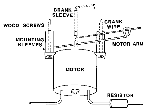
Figure A Installed Motor
|
SWITCH MACHINE PARTS
|
| 1 | Geared motor, 3v DC |
| 1 | Brass motor arm (loop on one end) |
| 1 | .030" steel crank wire |
| 1 | 1/16" brass tube (crank sleeve) |
| 1 | 1200 ohm resistor (for 12v supply) |
| 2 | Mounting sleeves |
| 2 | #5 x 1-1/2" wood screws |
|
REQUIRED TOOLS & SUPPLIES |
| Screw driver (Phillips) |
| Drill and 1/16" bit |
| File |
| Needle-nose pliers |
| Soldering iron (optional) |
| and Rosin core solder |
| Or alternately, ACC "Super Glue" |
|
|
Please read the instructions carefully. These tips will save you time and
effort. It is possible to permanently damage the motor if too much voltage
is applied! This is a 3 volt DC (direct current) motor. It should NOT be
attached to AC (such as Aux. power).
|
CRANK POSITION: Your first task is to decide how to attach
the crank to the throw-bar of the turnout. If you are installing the machine
on an existing turnout, or if you are not concerned if the crank wire will
be (slightly) visible, follow the directions in Step A. If you wish
to hide the crank completely, follow Step B.
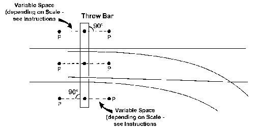
STEP A. Top of Tie Mounting:You can have the crank
pivot from any point marked "P" on Figure B.
The "line" between the pivot point and the hole you wish to use in
the throw-bar must form a 90° angle to the throw-bar (the turnout
points should be about midway, as shown in Figure B). The
distance between the throw-bar and the pivot point (P) varies with your
scale: about 3/8" for "HO"; 1/2" for "O";
1/4" for "N" and so forth. This is not a critical
measurement, but a general rule of thumb. Adjust this to match your particular
turnout. Drill a 1/16" hole through your roadbed and underlying benchwork
at your pivot point (P) This hole should be as near to vertical as possible.
Continue with "INSERTING THE CRANK SLEEVE".
Figure B Pivot Hole Locations
STEP B. Optional Hidden Mounting: If you
haven't yet installed your turnout, you can make provisions to completely
"hide" the crank. First, mark surface of your roadbed where
the turnout throw-bar will be.
Next, place a mark where you want the crank pivot point- you can
have the crank pivot from any point marked "P" on
Figure B. The "line" between the pivot point
and the hole you wish to use in the throw-bar must form a 90°
angle to the throw-bar (base this on points about midway between each outside
rail, as shown in Figure B). The distance between the
throw-bar and the pivot point (P) varies with your scale: about 3/8"
for "HO"; 1/2" for "O"; 1/4" for "N"
and so forth. This is not a critical measurement, but a general rule of
thumb. Adjust to match your particular turnout brand.
Drill a 1/16" hole through your roadbed and underlying benchwork
at your pivot point (P), this hole should be as near to vertical as possible.
Mark a box around the outside of the pivot hole and where the throw-bar
hole will be- this box should be 1/2" wide, and as long as necessary.
Use a router (or sharp chisel) to remove the roadbed in this area to a depth
of 1/8". Reset the router to a depth of 1/16", and make a
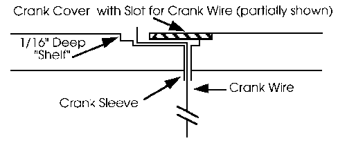
"shelf" around the original hole (see Figure C
this shelf will hold a piece of styrene or wood to conceal the crank).
Figure C Hidden Crank Wire
INSERTING THE CRANK SLEEVE: Locate the short piece of
1/16" brass tubing (crank sleeve). Slip it into the pivot hole.
The top of the tube should be flush with the top of the ties (or flush
with the bottom of the crank pit, if installed under the turnout),
and the bottom of the tube should not extend more than 1/8" under
the benchwork (don't worry if the tube is too short). If the tube slips
too easily in and out of the hole, glue it in place.
PREPARING THE CRANK WIRE: Locate the .030" steel crank
wire. File any burrs on the ends smooth. If you are installing the crank on
top of the ties, bend the crank as shown in Figure D. The
little bend on the end should be 1/32" for N or HO, 1/16" for
larger scales. This fits into the throw-bar. Remember the variable space
depends on your scale- we visually line ours up with the sleeve in the pivot
hole before bending. Be sure and use a good pair of needle-nose pliers so the
bends are sharp. Drop the wire into place and make sure it moves the
throw-bar freely. Remove the crank wire for now.
It may take several attempts to get the proper bend on the crank wire.
This wire is a little longer than needed, so you clip off the unusable bend
and try again.
If you are installing the crank wire under the ties, bend the wire as shown
in Figure C and E. Remembering the variable space depends on
your scale- bend the wire accordingly. If you will be using a prebuilt turnout,
drop the crank wire through the pivot hole, and set the turnout in place
(but do not install it). The crank should move the throw-bar freely. Remove
the turnout and crank wire for now. You will want to prepare a crank cover
from 1/16" thick wood or styrene stock to fit on the "shelf"
around the crank pit. This cover will need a narrow slot in it to allow
the crank to move freely under the throw-bar (the slot should be under the
throw-bar). The cover can be painted dark and ballasted later.
Figure D Crank Wire Bends Figure E
ATTACHING THE MOTOR ARM: Locate the motor arm. Slide the motor
arm through the hole in the motor shaft so the loop is 2 inches from the shaft.
The loop can point up or hang down (see Figure A). You can either
ACC ("Super Glue") the motor arm to the shaft or solder it in place.
Soldering is preferred for durability (if you ACC this assembly, be sure
NO ACC drips down the shaft into the motor!).
To solder this assembly, use flux to help the rosin core solder flow. Hold
the tip of the iron to the joint for several seconds, and then apply a strand
of solder onto the joint. Solder should melt and fill joint nicely. Remove the
iron. Don't leave it on too long or damage may result. Polish the shaft and
joint with a little household oil.
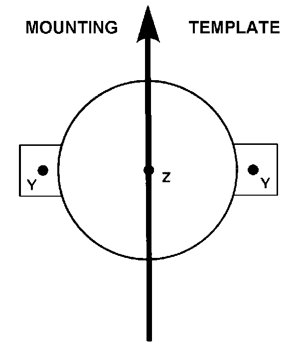
PLACING THE MOTOR: Find the mounting template (if you purchased
a single SwitchMaster, it is part of the package). Put a small hole exactly at
point "Z" on the template. Drop the crank wire through the pivot hole
and center the template under the benchwork so the crank wire comes through point
"Z" - tape or hold the template in place.
If you have many switch machines to install, fold the template in half across
points "Y" and "Z". Then simply hold it when drilling the
mounting holes at the "Y" points.
The crank and motor arm (indicated by the arrow) can point in any
direction (your benchwork or other switch machine(s) may determine which
way the motor arm points. See MOUNTING VARIATIONS if you cannot
fit the motor directly under the pivot point). Extend a line out from the arrow
onto the bottom of your benchwork to indicate which way the motor arm will point.
Drill shallow 1/16" holes at each "Y" point for the mounting
screws. Remove the template.
INSTALLING THE CRANK WIRE: Be sure the crank wire is placed
into the brass tube, and the small end is hooked into the throw-bar (if you
are installing this under the turnout, you can now permanently install
the crank cover and turnout).
Under the benchwork, pull the crank wire tight and bend it with your thumb
90° from the base of the hole into line with the directional mark you just
made. Study Figure A if you have questions.
ATTACH THE RESISTOR: It will be handy to attach the resistor
to the motor before we install it. Solder the 1200 ohm resistor (provided) in
series with the positive lead on the motor.
Our motor actually operates on 3v DC. The resistor provided assumes a 12v
DC power supply will be used. See TESTING THE MOTOR if you are
not certain of your power supply, or if you will be using a different voltage.
It must be properly adjusted.
INSTALLING THE MOTOR: Use the 2 wood screws and mounting
sleeves to install the motor. Do not over tighten the screws! Be sure the motor
arm is in line with the mark you made under the benchwork. Slip the crank wire
into the motor arm loop. If crank wire tends to slip out of the loop, squeeze
the loop to close the gap.
WIRING THE MOTOR: You have two wiring choices:
A. STANDARD DC, SINGLE UNIT POWER SUPPLY (Figure F) Attach
wires to the resistor and the motor's negative lead and run the wires to a
double-pole, double-throw (DPDT) switch. Wire the switch as shown in
Figure F, and wire the switch to the 12 volt, DC power supply
(such as Radio Shack #22-127).
|
SwitchMaster offers several DPDT switches and options:
|
| Part #1106 / TG-1 | SwitchMaster Toggle Switch - with red handle |
| Part #1107 / TG-2 | SwitchMaster Toggle Switch 2-pack |
| Part #1108 / TGB-6 | Black Toggle Handles (6) For color differentiation |
| Part #1109 / TGW-6 | White Toggle Handles (6) For color differentiation |
| Part #1110 / PB-1 | Constant Contact DPDT Push Button Switch |
| Part #1111 / PBB-2 | Black Push Button Caps (2) For color differentiation |
| Part #1112 / PBW-2 | White Push Button Caps (2) For color differentiation |
Figure F Standard Wiring
B. SPLIT POWER SUPPLY (Figure G) If you plan having a large number of switch motors,
you may want to consider using a split power supply system. This will reduce wiring and allow you
to use less costly single-pole, double-throw (SPDT) switches. You will, however, need
two 12 volt DC power supplies (such as Radio
Shack #22-127). Wire the motors and switches as shown.
Figure G Split Power Supply
TESTING THE MOTOR:
|
NOTE: Although certain power supplies are rated as 12 volts, they may be
higher. We have found some units rated at 12 volts actually produce 20
volts- enough to strip the gears in the motor unless proper resistance
is provided. Use the simple time test described below to see if your power
supply is delivering too much power.
|
We have tried to provide you with a 1200 ohm resistor (brown, red, red, gold)
that will work with most power supplies. If the switch machine is too fast
(quicker than 4 to 5 seconds to throw the points) or too slow, you may need
a different resistor.
Disconnect the switch machine if it runs too quickly!
If you are working outside the 4-5 second movement, measure the voltage
at the power supply with a load on it (such as the motor and included resistor).
Multiply this voltage by 100. This will roughly be the resistor size you need
(for example, 12 volts = 1,200 ohms; 16 volts = 1,600 ohms; etc.). You may need
to adjust this by +100 ohms, but once you find the right resistor,
it will work with every SwitchMaster motor you have connected to your power
supply. Replacement resistors are inexpensive and easy to find at a store such
as Radio Shack.
ELECTRICAL INFORMATION ON THE MOTORS: Do not be concerned that
your motor will be damaged by having constant power to it, as this motor is
designed to stall! In the stalled mode, the motor only draws about 10
milliamps. A 12 volt DC, 1 amp power supply will support 100 SwitchMaster
switch machines!
OHM'S LAW
E = I x R Where E = voltage, I = current and R = resistance
Just in case you wanted to know.
CONNECTING PANEL LIGHTS AND SIGNALS: You can use the constant
power on the SwitchMaster to power your panel lights and trackside
signals! This eliminates complicated wiring and additional contacts! Figure
H explains the wiring for these additions (but remember this will reduce
the number of switch machines you can run from a single power source). Our
list of accessories includes panel lighting kits and signal power converters.
Complete installation instructions are included with all accessories.
|
SwitchMaster offers these control panel lighting and signal accessories:
|
| Part #1102 / PL-2 | Panel Lighting Kit - 2 pair Red and Green LEDs |
| Part #1103 / DL-2 | Bi-color LEDs - 1 pair dual color (red/green) LEDs |
| Part #1104 / SG-2 | Signal Kits - converts SM power to block signals (2) |
| Part #1105 / MR-6 | LED Mounting Rings (6) |
Figure H Accessory Wiring
OTHER AUXILIARY CONTACTS: With the SwitchMaster, in
almost all cases a positive contact is made between the points and outer rails,
eliminating the need for power routing to the points. If your turnout
is one of the few that does require power routing, or if you need auxiliary
contacts for some other purpose (to automatically reverse polarity to a track
block, for example), we suggest using our Power Routing Contact #1101/PR-1.
This is a 3 amp micro-switch that mounts on the motor, and is triggered as the
motor arm changes positions.
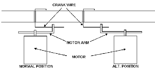
MOUNTING VARIATIONS: You may need to offset the placement of
your switch motor because of benchwork or other considerations. Figure
J shows an alternate choice for mounting the motor. Note that the motor
retains enough torque to operate in this configuration. You can also employ
bell cranks, flex-tubes and long wire throws.
Figure J Alternate Mounting
Maintenance
Actually, there is little to maintain with you SwitchMaster switch machine.
The motors were designed and constructed for durability and long life. Because
they are low voltage (3 volts DC which we supply through the resistor from your
12 volt power supply) there is no problem of overheating to worry about, they
simply move this way or that way, and stall out once thrown. It is a good idea
to cycle them from time to time as they may tend to "stick" a little in their
normally closed (mainline) position if left there year after year. A little
help and some cycling is usually all that is needed to get them working once
again.
The gears are completely enclosed to keep them free of dirt and lint so
there is no required maintenance there. Really, about all you have to do
is use them!
Replacement motors, mounting and linkage hardware are available.
© 2003 - Builders In Scale / SwitchMaster
|