|
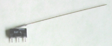
Part #1101 PR-1 Power Routing Contact
Auxillary contacts for switching power to points, frog, and/or blocks, etc..
High quality, SPDT, fully enclosed, industrial. Rated at 3 amp.
INSTALLATION INSTRUCTIONS
This power routing micro-switch can be used to automatically reverse a block
of track power, or to power points and/or frogs with poor electrical contact. In
either case, the switch machine movement is used to throw the micro-switch. This
switch attaches to the motor itself or to the underside of the layout.
These are high quality, fully enclosed SPDT (on/on) contacts rated at 3
amps and built for tens of thousands of throws.
Before installing the switch, let's discuss frog wiring. Depending upon which
way your turnout is throw, we want the contacts to route the correct power to
the frog, which is otherwise isolated. On some turnouts power is fed through the
points. SwitchMasters are good for this because the apply a constant firm pressure.
Auxillary contacts are needed if the points are dirty or in the case of modified
"DCC-friendly" turnouts where the points have been hard-wired to the
outside rails to eliminate possible shorts, leaving the frog completely isolated.
Whatever the case, the frog's polarity must be the same as the track alignment.
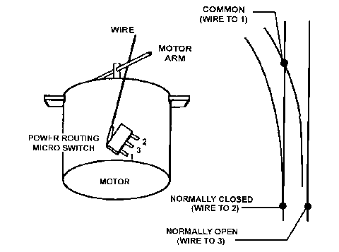
Pin 1 (nearest the hinge) is the common contact. It switches back and forth with
the other two pins. Pin 2 (farthest from the hinge) is normally closed (meaning
electricity will flow between it and with pin 1). And pin 3 (middle) is normally
open (electricity will not flow). When the switch is activated the circuit is
reversed, pin 3 opens and pin 2 closes.
Okay, so let's connect pin 1 to the frog. Pin 2 goes to the outside rail of
the normal route (straight or main), and pin 3 connects to the diverging route's
(curved or siding) outside rail. Pretty simple. If you are experiencing a dead
short most likely you need to reverse pin 2 and 3.
Before installing the switch, throw the switch machine to the mainline
(or "normally open" position). The power routing contact should be
triggered when the turnout points are midway in their movement (this prevents
a momentary short through the points). Experiment with the timing and
placement of the contact (if attaching to motor, place it near the bottom of
the motor at a slight angle, with the turnout in the normally open position).
Once you've determined where the switch should be placed, glue it in place
using ACC, hot glue, or a silicone type adhesive. After attaching the switch,
if it isn't triggered at the exact moment you desire, the brass wiper wire can
be slightly bent as your final adjustment.
Alternately, the switch can be attached to the underside of the layout. Use
the same guidelines above for determining its position.
A number of power routing contacts can be "stacked" by gluing them
together if multiple contacts are required.
Figure A Power Routing Contact Wiring
|